Resolving Esthetic Problems
The Double Casting Technique
The following patient treatment demonstrates one laboratory process used to overcome problems encountered when implants are aligned in unusual positions. These problems often become more apparent at the laboratory stage rather than in the clinical setting.
Laboratory design plan
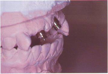
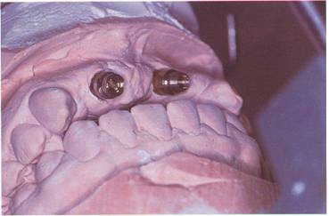
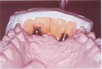
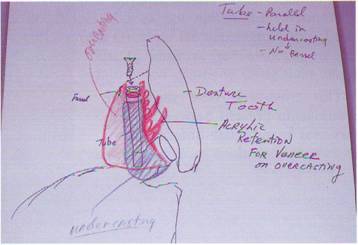
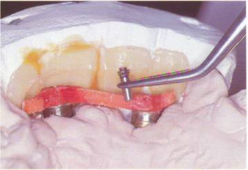
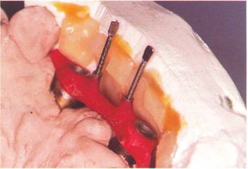
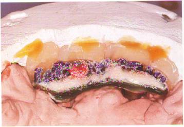
It is evident in the framework's design stage that the fixture placement prevents a normal or traditional restorative approach. When the gold cylinders are placed on the brass replicas of the master cast, the guide pins protrude into the middle of the anterior teeth (Figs. 9-3 and 9-4). Continuing with the guide pins in this position destroys the labial surfaces of the teeth, creating an unacceptable esthetic result. Also, the patient's high lip line requires special placement of the cervix of the teeth in relation to the ridge mucosa. Denture teeth are selected and diagnostically set to evaluate esthetics (Fig. 9-5). When the diagnostic wax-up is completed, the framework design requires a double casting technique. This consists of an implant-retained substructure barl securing an overcasting with screw and tube attachments (Fig. 9-6) (see Chapter 4). This design enables the castings to have both a firm anchor to the implants and to avoid screw access openings in the labial surfaces of the restorative teeth.
Method of fabrication
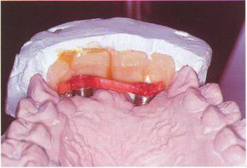
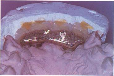
The substructure casting connecting the gold cylinders is constructed with plastic bars and DuraLay. The tube portion of the tube screw attachment is secured to the bar with DuraLay while being held parallel to the path of insertion. This path is determined by the incisal edge position and labial surface of the restorative teeth (Fig. 9-7). The path of insertion is also milled into the lingual and labial surfaces of the bar (Fig. 9-8). A labial tooth matrix is used here to determine the clearance available for the screw attachments (Fig. 9-9). When the tubes are positioned, the processing screws are lubricated and inserted. After final waxing, the bar is sprued, invested and cast with a Type IV gold alloy (T-IV-L, Nobelpharma). The bar is then carefully devested and all surfaces are finished (Fig. 9-10). The bar is steam cleaned and autoclave sterilized for a casting try-in (Fig. 9-11). Following a successful clinical try-in of the substructure bar, the overcasting is fabricated. The base or foundation for this pattern is an 0.3 mm thick plastic disc which is heated and vacuum formed over the substructure bar with a Dentsply Vacupress (Dentsply International). This produces superior results in the areas of stability and removal of the pattern. This pattern is carefully trimmed, and the end of each tube is exposed and the round ferrules luted to the pattern with self-cure resin.
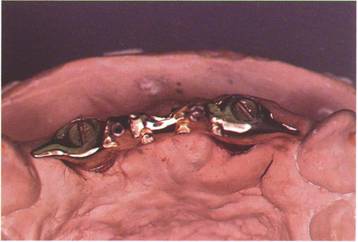
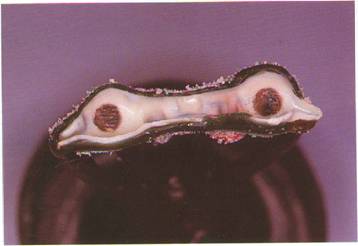
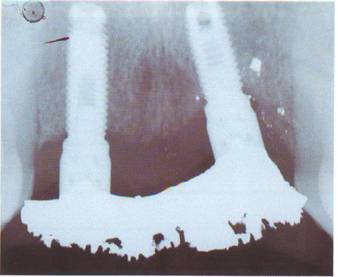
Finally, retention rods and loops are attached and the pattern is coated with retentive beads (Fig. 9-12). The finish line between gold and acrylic is now carved in and formed into a bezel shape. A final check with the tooth matrix is helpful here to insure minimum bulk of the overcasting pattern. The pattern is then sprued up, invested, and cast using the same Type IV gold alloy used for the substructure (Fig. 9-13). After careful devesting and finishing, the overcasting is seated on the substructure and then rechecked with the tooth matrix for labial clearance (Fig. 9-14). Again cleaned and sterilized, both castings are tried in the mouth and checked radiographically for accuracy (Fig. 9-15). The teeth are then processed to the overcasting with a quality heat-cured acrylic (Hi-I, Fricke Dental Manufacturing). Following acrylic finishing and final polishing, the double casting screw-retained T.I.P. is prepared for delivery (Figs. 9-16 and 9-17).
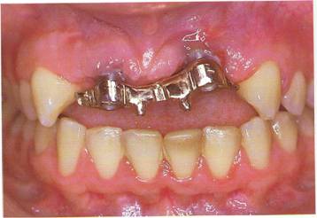
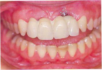
The clinical appearance of the prosthesis shows one implant visible at its junction with the bridge. Also, the acrylic in the interproximal area does not match the surrounding mucosa. This condition frequently calls for the use of a Gingival Replacement Unit2 (Figs. 9-18 and 9-19). Using the Gingival Replacement Unit to improve the esthetics of the prosthesis works very nicely. This small prosthesis is fabricated chairside using light-cured resin (Figs. 9-20 and 9-21).
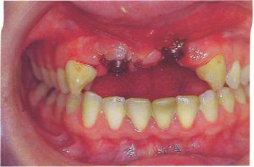
This patient exhibits a partial edentulous area in the maxillary anterior area of teeth #'s 7, 8, 9, and 10.
Due to underlying bone structure, the two Bdinemark implants cannot be surgically placed in the preferred position.
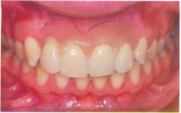
This cross-arch view shows the relationship present between maxil-lary and mandibular anterior teeth in centric occlusion.
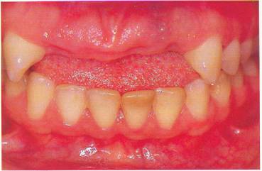
A frontal view further demon¬strates the difficult dimensions that must be overcome to achieve the desired esthetic result. The implant in the area of teeth #'s 7 and 8 is the mo,st labial of the two. A smaller gold cylinder with a flathead screw is placed here to conserve interarch space.
This lingual view shows the den¬ture teeth held in position by a plas¬ter matrix. Note the hollow areas cut into the teeth to create room for the prosthesis.
Each component of the restora¬tion is shown by this diagrammatic drawing.
A plastic bar is attached to the hard DuraLay rings with fresh resin. The tooth matrix is used here to help in the accurate placement of the bar.
The female tube attachment is positioned parallel to the desired path of insertion.
Processing screws are placed in the fixed tubes and checked for clear¬ance. The bar is then milled parallel on the lingual and labial surface.
An occlusal view of the finished substructure bar shows small distal cantilevers that improve the stability of the ,overcasting.
Notice the parallel walls and good marginal fit at the implant junction in this labial view of the clinical try¬in of the substructure bar.
The finished overcasting pattern is checked for labial clearance with the tooth matrix.
The internal portion of the pattern is shown here before the investing procedure.
Both castings are seated on the master model and again tested for clearance with the tooth matrix.
Both castings are tried intraorally and verified by radiograph for fit.
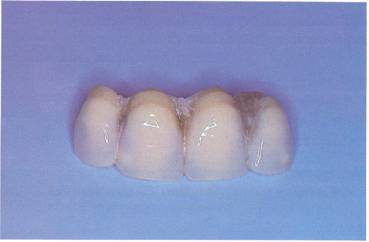
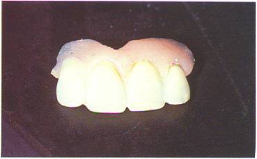
The processed and finished pros¬thesis is shown in this labial view.
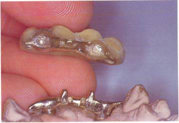
Both castings are examined prior to packing and delivery.
A postoperative view of the patient with the prosthesis inserted.
The custom-fitted gingival replace¬ment unit is light cured at chairside to insure accuracy.
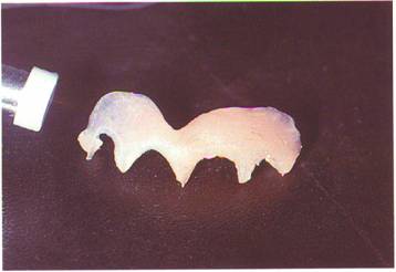
Some slight finishing and polish¬ing is done to perfect the Gingival Replacement Unit.
With the entire prosthesis in place, a comparison with Figure 9-18 illus¬trates a dramatic improvement in esthetics created by the Gingival Replacement Unit.