The Slant-Lock Retention System
The Slant-Lock System is marketed as the first system which gives the stability of a screw-retained fixed bridge and the benefits of a removable prosthesis. Since the overdenture is removable by the patient, the substructure bar and cylinders, as well as the surrounding tissue area, are easily accessible for hygiene maintenance. This is a good treatment plan for patients with limited manual dexterity. As in other overdenture applications, the fully extended denture base can replace lost bone and tissue. An important consideration is the vertical dimension. The latch and housing must be placed below the cervical of the prosthetic teeth to achieve the proper esthetic results. Space requirements can be determined after the initial wax setup and fabrication of the matrix are complete.
In a maxillary restoration, the Slant-Lock gives the esthetics of a denture flange and the support of a full natural lip contour. This system solves the phonetic problem of air passage or hissing that is sometimes present with the fixed denture bridge format.
The wax setup must be anatomically correct. Any deviation in thickness or contour of the base will put the latch in an incorrect or possibly undesirable position.
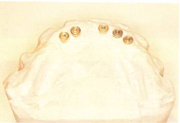
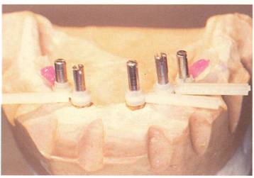
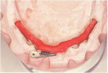
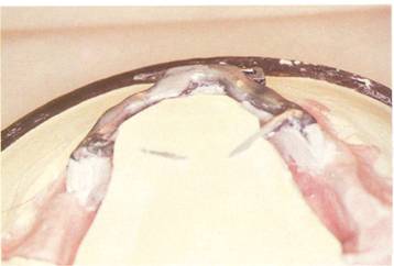
This mandibular master cast has five Branemark fixture replicas.
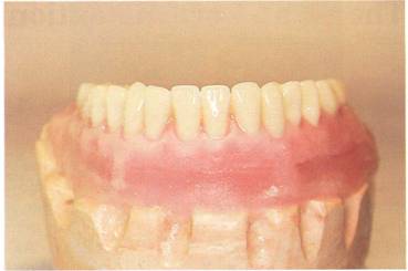
Denture' teeth are selected (Bioblend lPN, Dentsply) and a wax setup is completed. The master cast is keyed and lubricated in preparation for a matrix.
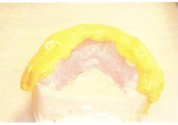
Ramitek material is mixed and the matrix is formed.
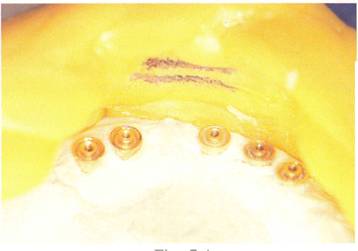
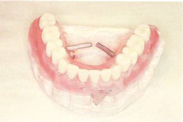
The wax setup is removed from the cast and the general area of the latch is determined and marked. The implant spacing is a general indicator of where to place the latch. The optimal placement of the latch is in the anterior region. The prosthetic teeth must be above the position of the latch.
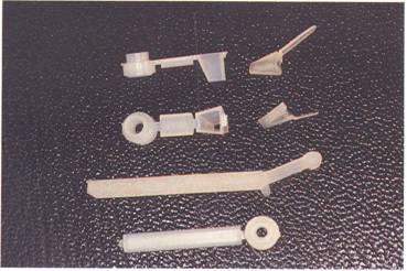
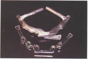
The castable components include from the top: cylinder with adjustable runner bar, female attachment, male attachment; occlus?l view of the same attachments: latch bar, regular cylinder with bar.
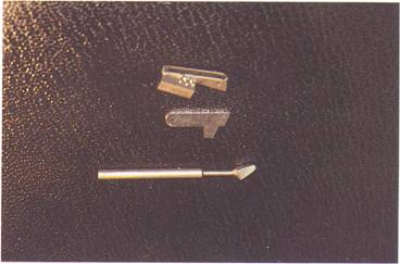
The metal components from the top: latch housing, latch, paralleling mandril.
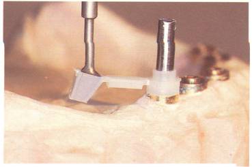
The cast is mounted on a surveying table with fixture replicas horizontally level and as vertically parallel as possible. Lightly screw the female attachment cylinder into place, leaving room for adjustment. Place the female runner bar attachment on
the ridge. The paralleling mandril is placed in the surveying arm (J. M. Ney Co.) and then in the attachment. Plastic gates can be bent to adjust 'the angle of the pattern to the cast. Tighten the guide pin to secure the loose plastic cylinder, and recheck the mandril.
NOTE: Do not overtighten guide pills.
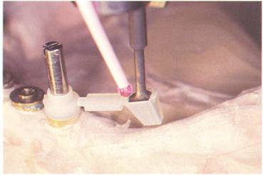
After the position is satisfied, Zapit is used to secure all bendable parts of this runner bar. Do not allow
Zapit to enter the female portion of this attachment.
The remaining cylinders with bars are loosely secured with guide pins. The predetermined area for the latch bar is kept open.
Using a heated razor knife, the bars are cut to fit between each cylinder.
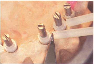
Guide pins are tightened on each cylinder and luted together with Zapit.
The latch bar is designed to be square except for a ISO slant on the lingual aspect. The 15° side is marked, since after the holding tab is cut off, it is difficult to determine the difference between the labial and lingual.
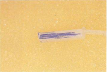
The latch bar is placed and measured to size. The bar should extend the entire width of the cylinders in the labial position.
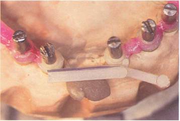
The bar is cut to correct size.

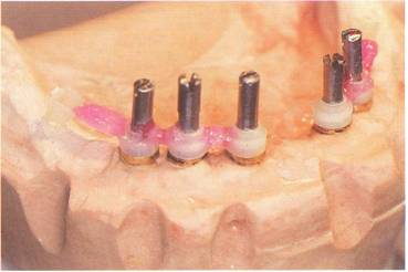
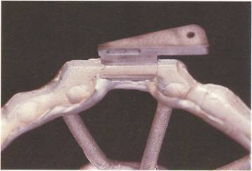
The latch bar with metal housing and latch is held in place with utility wax. The bar must be kept in a level position. The matrix is placed on the master cast and the position of the "latch bar and housing is checked for accuracy. The latch must touch the labial portion of the matrix and in the area of the mark. When the position is correct, the bar is secured with Zapit.
The utility wax and latch housing are removed. The bar is waxed to final contour with a slight occlusal taper to accept the overcasting.
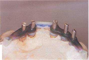
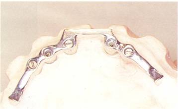
A labial view of the completed bar. Spruing, investing and casting procedures are carried out. A base metal alloy (Rex III, JenericPentron) is used.

The casting is then devested and cleaned following the protocol described.
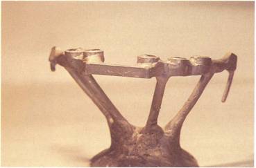
The undercasting is finished and polished. Minimal polishing should be done in the area of the latch bar, as this is geared to fit the housing for the locking latch.
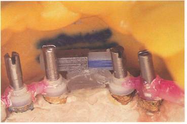
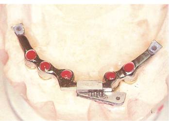
The distal male attachments should now be fitted to their female coun-terpart. Any descrepancies should be relieved until the males seat securely. The overcasting is ready to be fab-ricated. The screw access holes are filled in level with utility wax. The distal male attachments are placed, and the Slant-Lock housing is put into the proper position.
Soft DuraLa y is used to incorporate the distal male attachments and the Slant-Lock housing. When the mix of DuraLay can be hand manipulated, it is molded over and around the remaining parts of the bar. Care should be taken not to engage the undercuts of the primary bar. Soft excess DuraLay can be trimmed with a sharp scalpel-type knife. After the DuraLay has set, the overcasting must be carefully removed from the substructure. Any irregularity that prevents the frame from seating or releasing from the primary bar must now be eliminated.
The overcasting is sprued, invested and cast in the same alloy as the substructure bar. The temporary retention wings are waxed in for fram€work stabilization during investing and packing procedures.
The overcasting is diamond finished after the fit to the substructure bar has been satisfied.
Using the matrix, the denture teeth are set into the model with the substructure bar and overcasting in place. If possible, another try-in to verify esthetics and occlusion should be performed at this time.
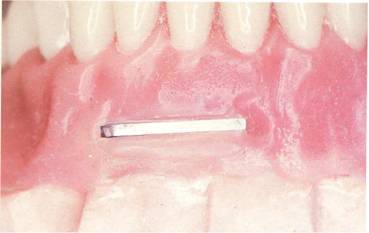
A close-up view of the latch in the anterior section of the wax-up. If it is necessary for esthetics, the latch can be silicoated and opaqued to match the pink acrylic.
The denture is flasked in the con-ventional manner and boiled out. Any undercuts in or around the substructure bar and overcasting should be blocked out at this time.
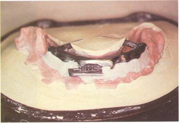
This lingual view illustrates the temporary retention wings embedded in stone, securing the overcasting to the substructure bar during the packing procedure. The restoration is now packed in the normal manner.
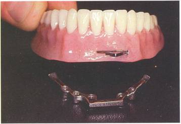
The processed denture is carefully devested and removed from the master cast. It is then finished and polished. A facial view of the restoration with the substructure bar is shown.
An internal view shows the metal overstructure incorporated in the processed acrylic.
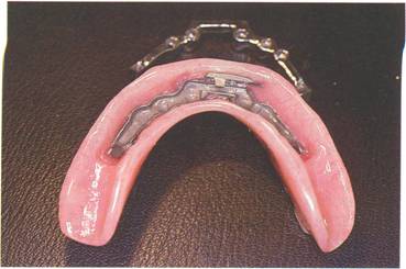
A lingual view with the retention wings cut and polished.

The prosthesis is illustrated with the Slant-Lock in open position ready for insertion.